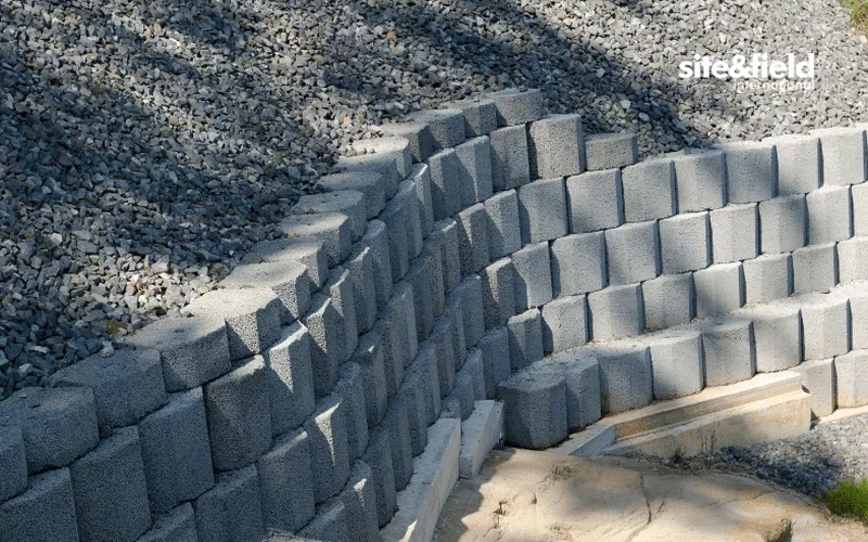
The flat coastal prairie around Corpus Christi hides a complex stratigraphy of Pleistocene Beaumont Formation clays overlain by recent bay and fluvial deposits. Designing a retaining structure here means confronting high-plasticity soils that swell after a tropical downpour and shrink during the August drought, creating lateral pressures far beyond textbook assumptions. The city’s average elevation of just 7 feet above sea level introduces a shallow groundwater table that complicates every excavation within the 78401 through 78418 zip codes. When a developer breaks ground near Oso Creek or along Ocean Drive, the retained soil mass must resist not only static earth loads but also storm surge hydrodynamics. Integrating a grain-size analysis early in the investigation pinpoints the silt-clay fraction that governs drainage design, while in-situ permeability testing quantifies the hydraulic conductivity needed to size weep holes and blanket drains behind the stem. A retaining wall in Corpus Christi is fundamentally a hydraulic structure as much as a structural one.
A retaining wall in Corpus Christi is a hydraulic structure first and a structural element second—if you don’t solve the water, the wall fails regardless of the steel.
Methodology and scope
A recurring mistake in South Texas construction is treating retaining wall backfill as generic fill material. The local Calallen and Flour Bluff areas contain lenses of fat clay with liquid limits exceeding 50 percent; placing this behind a cantilever wall without a granular drainage chimney guarantees hydrostatic build-up and eventual tilting. The design team at our Corpus Christi projects first classifies the retained soil per ASTM D2487, then runs consolidated-undrained triaxial tests to establish the effective stress parameters needed for a Coulomb or Rankine analysis. Wall types range from conventional cast-in-place cantilevers with a 0.4H base width for heights under 12 feet to mechanically stabilized earth (MSE) systems using galvanized steel straps when the right-of-way is tight along SPID or Crosstown Expressway.
Corpus Christi’s exposure category C per ASCE 7-22 adds a wind-driven lateral component that governs the stem reinforcement schedule, especially for freestanding walls above 8 feet. We model the combined earth-plus-surcharge-plus-wind load envelope using limit equilibrium software, checking sliding, overturning, and bearing capacity under both drained and undrained conditions. For projects within the 100-year floodplain, scour depth at the toe becomes the controlling factor; a 3-foot scour can reduce passive resistance by 60 percent, which is why we often specify a trench fill extending below the calculated scour prism.
Local considerations
IBC 2021 Section 1610 mandates that retaining walls resist lateral earth pressures, hydrostatic pressures, and surcharge loads—a combination that becomes particularly punishing along the Corpus Christi bayfront. The National Weather Service records storm surge events that elevate the water table by 4 to 6 feet within hours, instantly saturating backfill and tripling the lateral load on the stem. Wall failures observed after Hurricane Harvey in 2017 across the Coastal Bend region often traced back to inadequate drainage or underestimation of the passive wedge resistance in liquefied foundation soils. We evaluate the factor of safety against bearing capacity failure under rapid drawdown conditions, where the external water level drops faster than the backfill can drain, leaving an unbalanced hydrostatic head. For walls exceeding 6 feet adjacent to public rights-of-way, the Texas Board of Professional Engineers requires sealed calculations; we deliver a comprehensive package with global stability checks using Spencer’s method, including search surfaces that daylight into the excavation face.
Applicable standards
ASCE 7-22 Minimum Design Loads and Associated Criteria for Buildings and Other Structures (Chapters 3, 26–30 for wind; Chapter 15 for earth pressure), IBC 2021 Section 1807 Retaining Walls (limit states: sliding, overturning, bearing), ASTM D2487-17e1 Standard Practice for Classification of Soils for Engineering Purposes (Unified Soil Classification System), AASHTO LRFD Bridge Design Specifications, 9th Ed., Section 11 (Abutments, Piers, and Walls), adopted by TxDOT for state-funded projects
Frequently asked questions
How much does retaining wall design cost for a residential project in Corpus Christi?
For a typical residential retaining wall in the Corpus Christi area—say a 4- to 8-foot cantilever wall spanning 50 linear feet—the engineering design and sealed calculations generally range from US $1,090 to $3,800. The final figure depends on the wall height, the proximity to waterfront requiring scour analysis, and whether the City of Corpus Christi Development Services requires a third-party geotechnical report.
What type of retaining wall works best in the Beaumont Clay soils around Corpus Christi?
Cantilever reinforced concrete walls perform well because the foundation can be deepened below the active zone of seasonal moisture fluctuation. For walls over 12 feet, MSE walls with select granular backfill reduce the lateral load and accommodate differential settlement better than rigid structures. Drilled shaft walls (tangent or secant) are an option when excavation space is limited in downtown Corpus Christi.
How do you account for hurricane storm surge in the wall design?
We model a rapid-drawdown condition where the storm surge recedes faster than the backfill can drain. This creates an unbalanced hydrostatic pressure that adds 60–100 percent to the lateral earth load, depending on the backfill permeability. The factor of safety against overturning is checked at 1.5 under this transient load case per IBC 2021.
Do I need a building permit and sealed plans for a retaining wall in Corpus Christi?
Yes. The City of Corpus Christi requires a building permit for any retaining wall over 4 feet in height measured from the bottom of the footing to the top of the wall, or any wall supporting a surcharge. A Texas-licensed Professional Engineer must seal the structural calculations and drawings. Walls under 4 feet not supporting a surcharge are exempt from permitting but must still comply with setback and drainage ordinances.
How long does the design process take from site visit to stamped drawings?
A typical timeline runs 3 to 4 weeks. Week one covers the geotechnical boring and laboratory testing on the Beaumont Clay samples. Week two is devoted to stability analysis and structural modeling. The third week produces the drawing set and drainage details, with the final week reserved for internal quality review and the engineer’s seal. Expedited schedules are available for emergency slope failures or construction delays.